Title of Activity : Pulse Width Modulator ( PWM ) circuit and Triac BT 139.
Objective :
1) To understand how the PWM works.
2) To research and design the function of Triac BT 139.
Content / Procedure :
1) Make research on website about the PWM circuit & how to use it.
2) Design how to connect the PWM circuit with the micro-controller.
3) The function of Triac BT139 for using in the circuit.
Result and Analysis :
1) Pulse Width Modulator (PWM) circuit will receive decoded signal from PIC to control the heat, whereas the PWM is more like switch for heater.
2) The main component in this circuit is MOC3041M, whereas this device consist of infrared emitting diode optically coupled to a monolithic silicon detector performing the function of a zero voltage crossing bilateral triac drives.
3) BT139 are using in this circuit, whereas its glass passivited triacs in a plastic envelope,intended for use in application requiring high bidirectional.
4) Blocking voltage capability and high thermal cycle performance.
5) Typical used include motor control,industrial and domestic lighting, heating and static switching.
6) The maximum voltage triac can be supported is 500V and maximum current can support is 16A.
Conclusion :
By using PWM circuit, the heat control for the project will be efficiency & the process of project will run well.
PICTURE & DIAGRAM OF TRIAC BT139 & MOC3041M

a) Pin configuration of Triac BT139
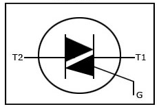
b) Symbol Triac BT139

c) Schematic diagram for MOC3041M

d) Figure shows about the zero voltage crossing
No comments:
Post a Comment